
If you have an old water tank monitor that only shows water levels through glowing lights, you can easily convert it into a smart device that reports to Home Assistant. This guide will walk you through the entire process, from understanding the circuit to writing the configuration.
Many older water tank monitors work with simple LED indicators that show different water levels (25%, 50%, 75%, 100%) or (10%, 20%, 40%, 60%, 80%, 100%) by lighting up corresponding light. While functional, they're not "smart" and can't integrate with modern home automation systems.
1. Requirements
1.1. Hardware
- Existing Dumb Water Tank Monitor
- ESP8266 NodeMCU (or similar ESP8266 board)
- 5V DC power supply for ESP8266
- Multimeter (for voltage measurement)
- Jumper wires
- Resistors (values depend on your LED voltage, see measurement step below)
1.2. Software
- Home Assistant with ESPHome add-on installed
- Basic knowledge of YAML configuration
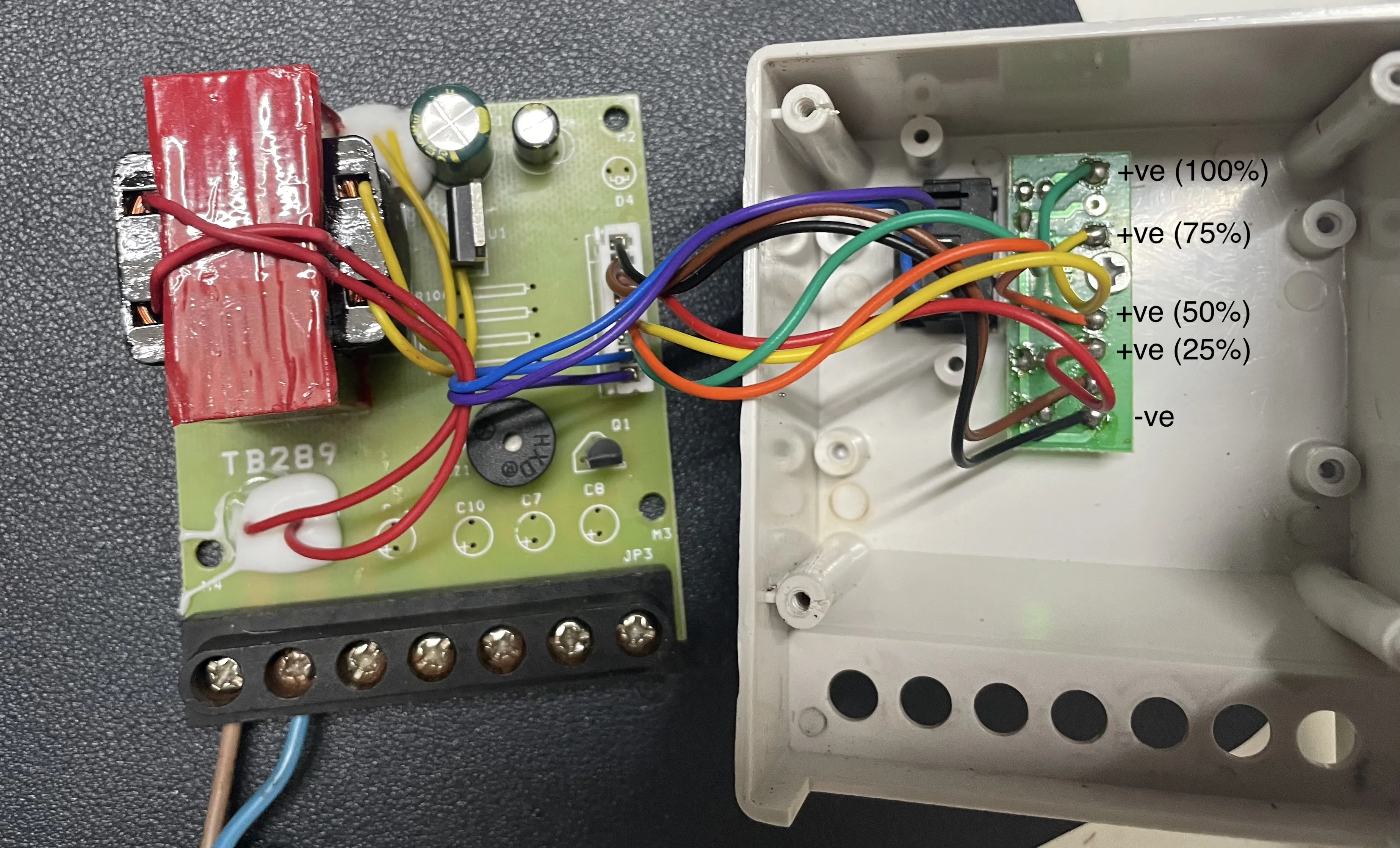
2. Measure the Voltage at Each LED
Before connecting anything to your ESP8266, you must know the voltage at each LED output. This ensures safety and helps you select the correct resistors.
If your water level monitor is using standard LEDs, then most of them are likely within the 3.3V limit depending on their color. Typically, Red LEDs are around 1.8V, Green around 2.0V, Yellow/Amber around 2.1V, Blue around 3.0V, and White around 3.2V.
If your water level monitor is not using standard LEDs, then the input voltage might vary. In that case, you should use a multimeter to measure the actual voltage. Once you know the correct voltage, you can choose the appropriate resistor value to match that voltage and ensure safe operation.
3. Wiring Everything Together (for LEDs <= 3.3V)
Here's how to connect all the components:
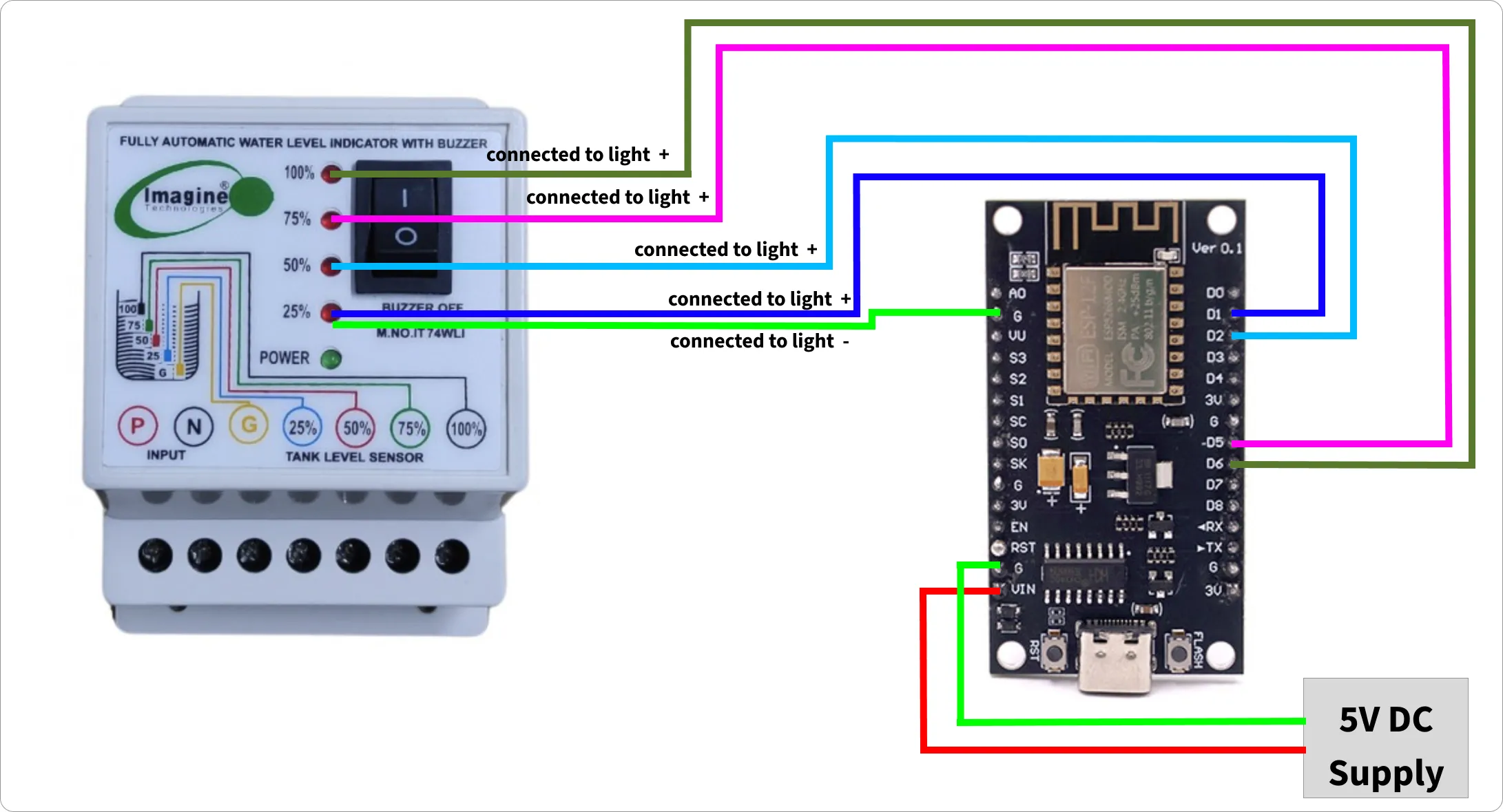
3.1. Power Connections
- 5V DC Power Supply (+) → ESP8266 VIN
- 5V DC Power Supply (-) → ESP8266 G
3.2. Communication Connections
- 25% LED (+) → D2
- 50% LED (+) → D1
- 75% LED (+) → D6
- 100% LED (+) → D5
- LED (-) → GND
Note: If your water level monitor has 6 levels, you can use pins D7 and D8 for the additional 2 levels.
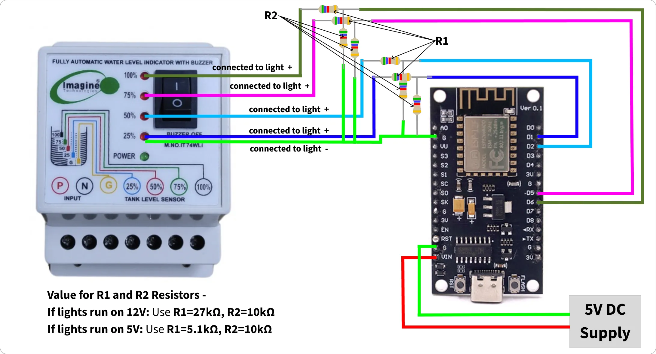
4. Wiring Everything Together (for LEDs > 3.3V)
Here's how to connect all the components:
4.1. Power Connections
- 5V DC Power Supply (+) → ESP8266 VIN
- 5V DC Power Supply (-) → ESP8266 G
4.2. Communication Connections
25% LED (+) → R1 → D2
                 ╵→ R2 → GND
50% LED (+) → R1 → D1
                 ╵→ R2 → GND
75% LED (+) → R1 → D6
                 ╵→ R2 → GND
100% LED (+) → R1 → D5
                  ╵→ R2 → GND
LED (-) → GND
4.3. Calculate R1 and R2 (Voltage Divider)
To safely step down a voltage for ESP8266 GPIO using a voltage divider. The formula relates the input voltage, desired output voltage, and resistor values:
Vout = Vin * (R2 / (R1 + R2))
- Vin - input voltage
- Vout - output voltage
- R1 - Resistor 1
- R2 - Resistor 2
Example -
- Vin = 5V (water monitor LED voltage)
- Vout <= 3.3V (required safe voltage for ESP8266)
- R2 = 10kΩ (a standard value for R2 e.g. 4.7kΩ or 10kΩ for low current draw)
R1 = R2 * ((Vin/Vout) - 1)
R1 = 10k * ((5V/3.3V) - 1) = 10k * (1.515 - 1) = 10k * 0.515 = 5.15kΩ
5. ESPHome Configuration
5.1. Update Configuration
- Setup ESP8266 for first use via USB using web.esphome.io
- Create a new device in HomeAssistant ESPHome, and append the following configuration:
# Binary sensors for direct light signal detection
binary_sensor:
  - platform: gpio
    pin:
      number: GPIO4  # D2
      mode: INPUT
    name: "Level 25%"
    id: level_25

  - platform: gpio
    pin:
      number: GPIO5  # D1
      mode: INPUT
    name: "Level 50%"
    id: level_50

  - platform: gpio
    pin:
      number: GPIO12 # D6
      mode: INPUT
    name: "Level 75%"
    id: level_75

  - platform: gpio
    pin:
      number: GPIO14 # D5
      mode: INPUT
    name: "Level 100%"
    id: level_100

sensor:
  - platform: template
    name: "Level"
    id: level
    unit_of_measurement: "%"
    accuracy_decimals: 0
    lambda: |-
      if (id(level_100).state) {
        return 100;
      } else if (id(level_75).state) {
        return 75;
      } else if (id(level_50).state) {
        return 50;
      } else if (id(level_25).state) {
        return 25;
      } else {
        return 0;  // No lights on = empty or below 25%
      }
    update_interval: 2s

text_sensor:
  - platform: uptime
    name: Uptime
    id: uptime_days
    format:
      separator: " "
      days: "D"
5.2. Flash and Test
- Validate the above config changes, fix any errors.
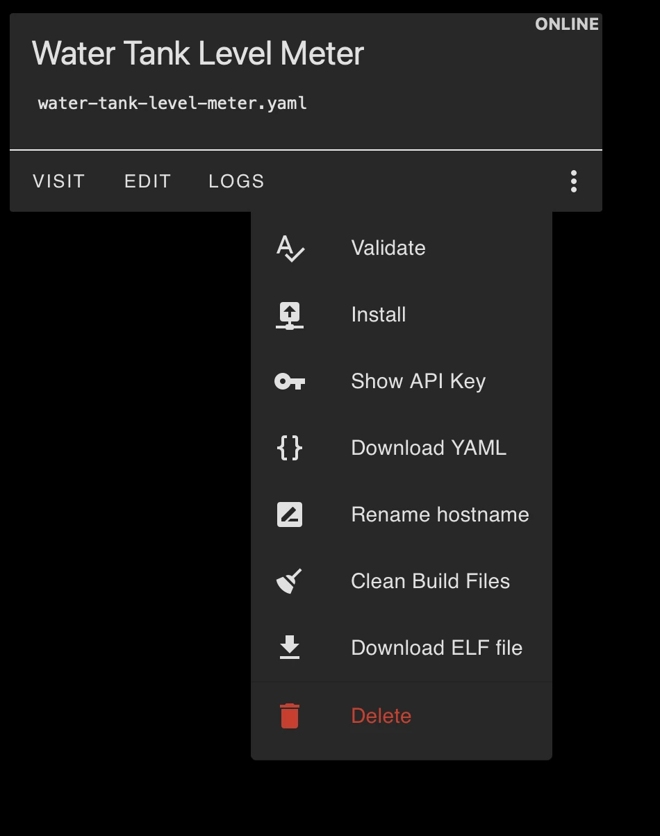
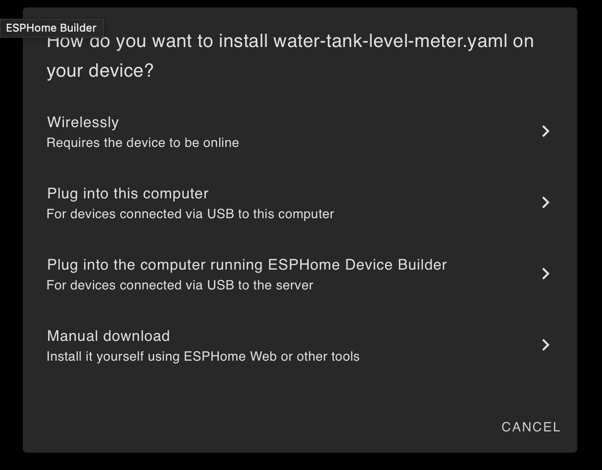
- Install the updated config wirelessly. If you're unable to install it wirelessly, then select last option manual download and try installing it manually using web.esphome.io.
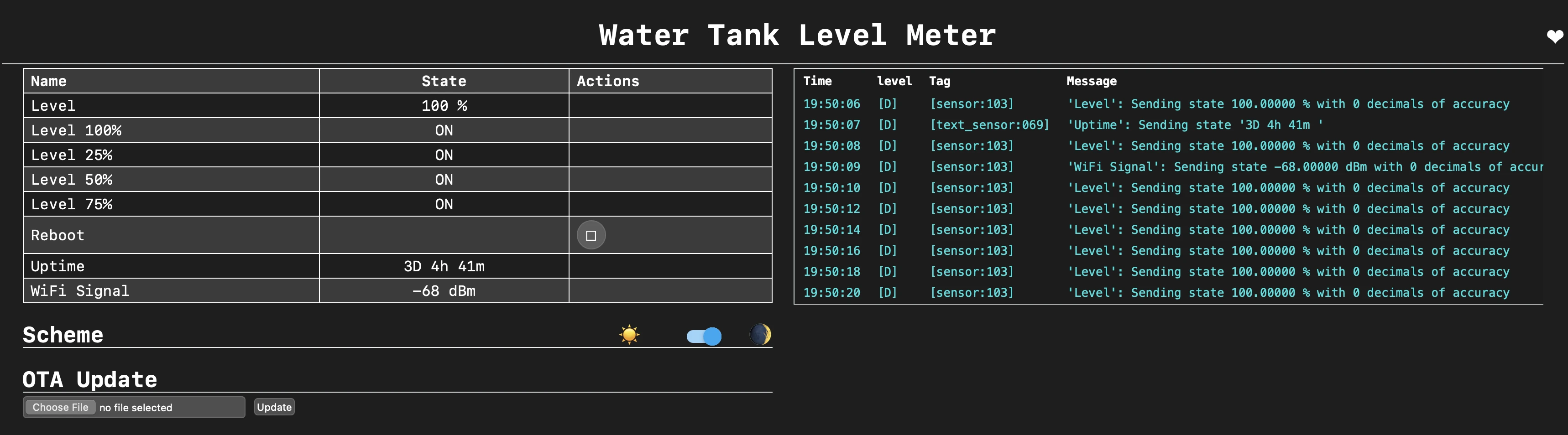
- Visit the ESP8266 IP assigned by your router (you can find this in your router's DHCP client list or in the ESPHome logs). You should be able to see something like this:
6. Add Device to Home Assistant
After successfully flashing your ESP8266 and confirming it's working through the web interface, you need to add it to Home Assistant to see all your water meter sensors.
6.1. Add Device
- Go to Settings
- Select "Devices & Services"
- Click the "+ ADD INTEGRATION" button
- Search for and select "ESPHome"
- Enter device details:
- Host: Enter the IP address of your ESP8266
- Port: Leave as 6053 (default)
- Click "Submit"
6.2. Verify Integration
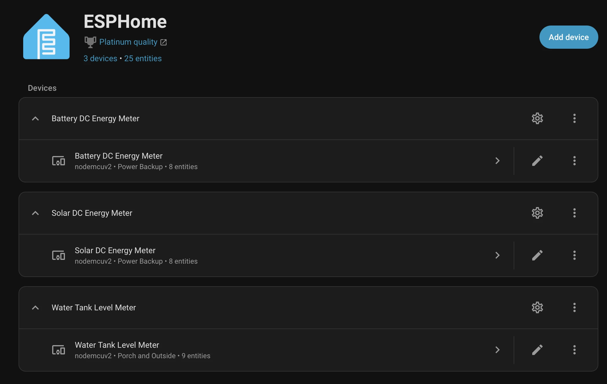
After successful integration, you should see the device listed like this.
You can open the device details to view its entities and their values.
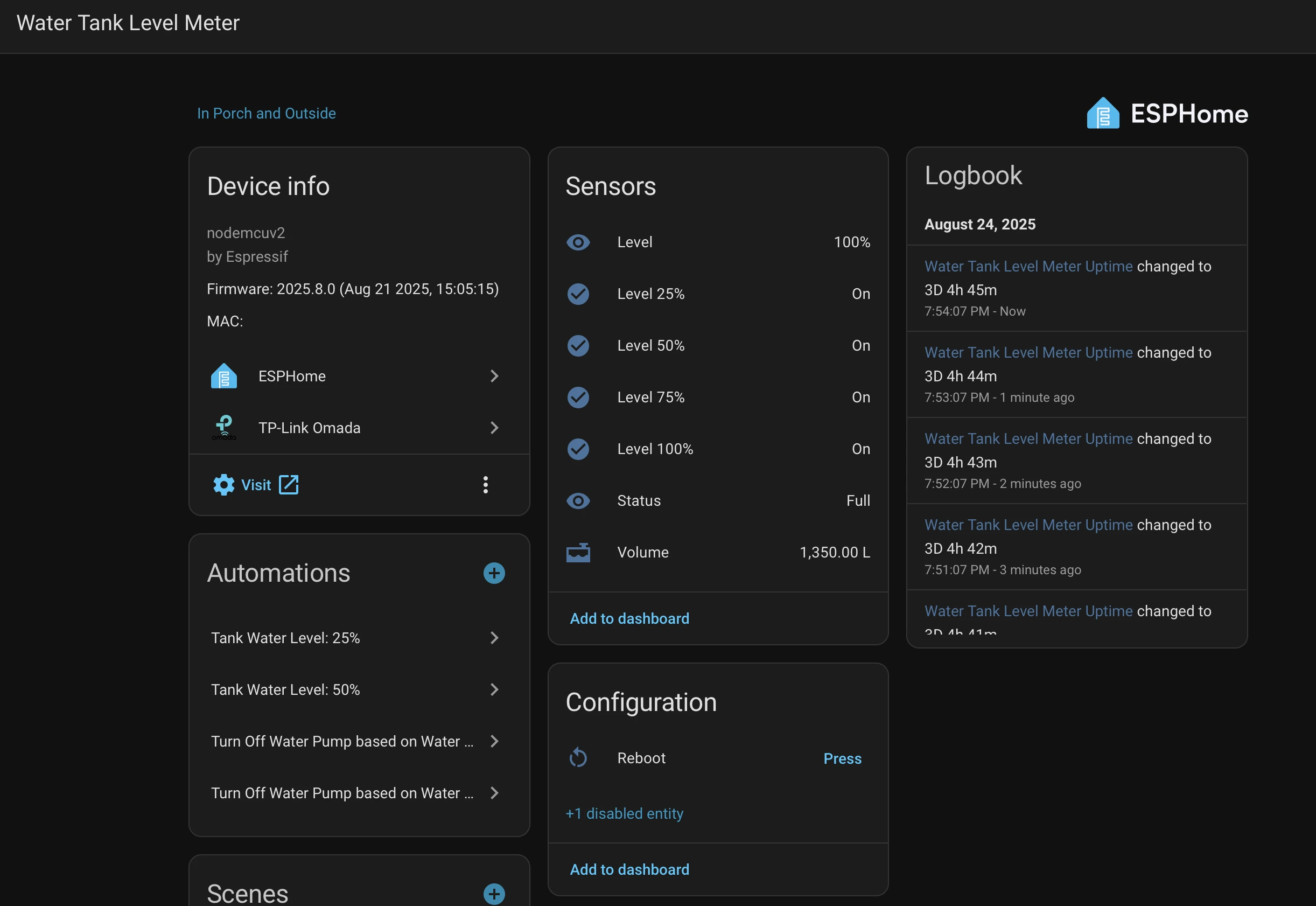
Now, you can create beautiful dashboards in Home Assistant to track your water tank level, set up automations based on levels.The system is very reliable once properly configured and can run for months without issues.