
If you want to monitor your solar system's performance and track energy production in real-time, this guide will show you how to build a reliable DC energy monitoring system. This guide is also apply to track battery system as well. We'll use the PZEM-017 DC meter, ESP8266 (NodeMCU), RS485 to TTL converter module, and integrate everything with Home Assistant through ESPHome.
1. Requirements
1.1. Hardware
- PZEM-017 DC energy meter with 300A shunt (or 50A/100A/200A depending on your needs)
- ESP8266 NodeMCU (or similar ESP8266 board)
- RS485 to TTL converter
- 5V DC power supply for ESP8266 and RS485
- 5V DC power supply for PZEM-017 (Optional. Only required if you need to measure below 7 volts)
- 1k-5kΩ resistor
- Jumper wires
- DC Source (Solar/Battery)
1.2. Software
- Home Assistant with ESPHome add-on installed
- Basic knowledge of YAML configuration
2. Wiring Everything Together
Here's how to connect all the components:
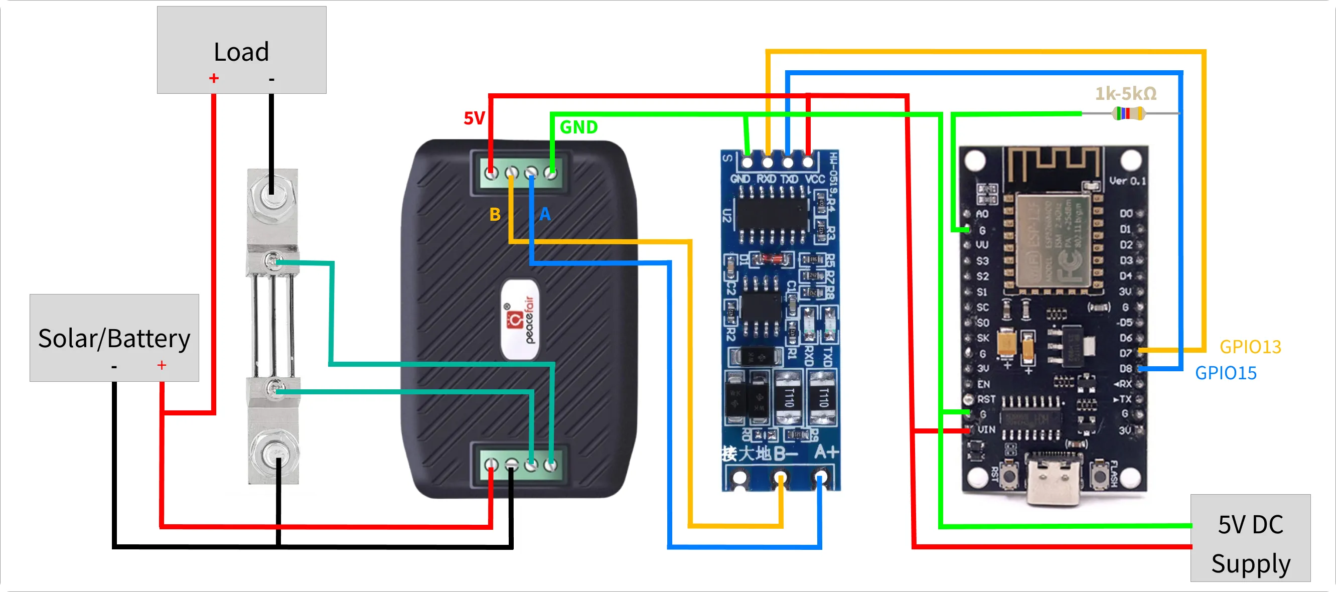
2.1. Power Connections
- 5V DC Power Supply (+) → ESP8266 VIN → RS485 VCC → PZEM-017 5V
- 5V DC Power Supply (-) → ESP8266 G → RS485 GND → PZEM-017 GND
- Solar/Battery (5-300V DC) (+) → PZEM-017 (+)
- Solar/Battery (5-300V DC) (-) → Shunt → PZEM-017 (-)
Note: If you need to measure less than 7 volts, you must provide a 5V DC supply to the PZEM-017 through the micro USB port.
2.2. Communication Connections
- ESP8266 GPIO13 (D7) → RS485 RXD
- ESP8266 GPIO15 (D8) → RS485 TXD
- ESP8266 GPIO15 (D8) → 1k-5kΩ resistor → ESP8266 G
- RS485 A → PZEM-017 A
- RS485 B → PZEM-017 B
Note: A 1k–5kΩ resistor (up to 10kΩ might work, but not tested) is needed to pull GPIO15 LOW during boot/reset. If GPIO15 is HIGH at boot, the ESP8266 won't start normally and may fail to boot or get stuck in the bootloader.
2.3. PZEM-017 Measurement Connections
- Install the shunt in series with your DC negative line (between solar/battery negative and load negative)
- Connect the shunt wires to the PZEM-017's current measurement terminals (order doesn't matter here).
Important: Make sure all devices share a common ground connection.
3. ESPHome Configuration
3.1. Update Configuration
- Setup ESP8266 for first use via USB using web.esphome.io
- Create a new device in HomeAssistant ESPHome, and append the following configuration:
uart:
  tx_pin: GPIO15
  rx_pin: GPIO13
  baud_rate: 9600
  stop_bits: 2

sensor:
  - platform: pzemdc
    current:
      name: "Current"
      id: current
    voltage:
      name: "Voltage"
      id: voltage
    power:
      name: "Power"
      id: power
    update_interval: 5s

  - platform: total_daily_energy
    name: "Daily Energy"
    id: daily_energy
    filters:
      - multiply: 0.001
    unit_of_measurement: kWh
    accuracy_decimals: 2
    power_id: power

  - platform: wifi_signal
    name: "WiFi Signal"
    id: wifi_signal_dbm
    update_interval: 60s

text_sensor:
  - platform: uptime
    name: Uptime
    id: uptime_days
    format:
      separator: " "
      days: "D"

button:
  - platform: restart
    name: "Reboot"
    id: reboot
3.2. Flash and Test
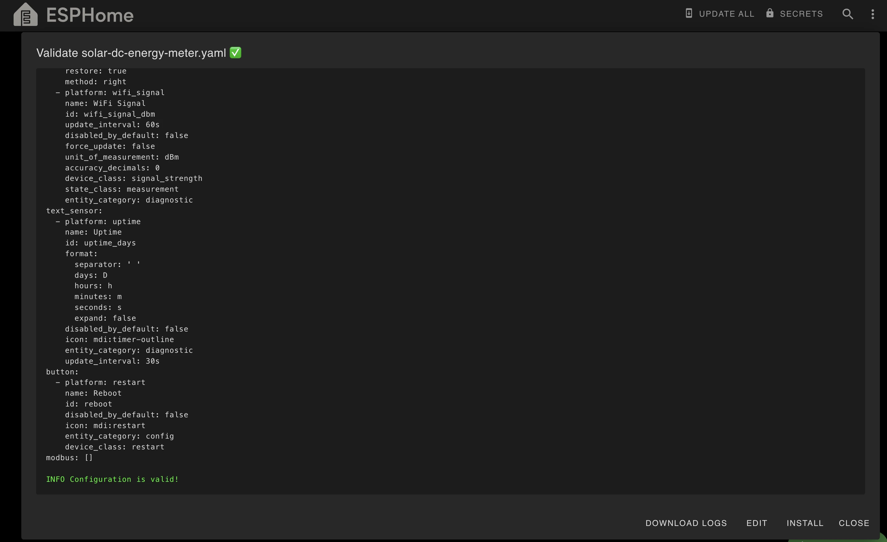
- Validate the above config changes, fix any errors.
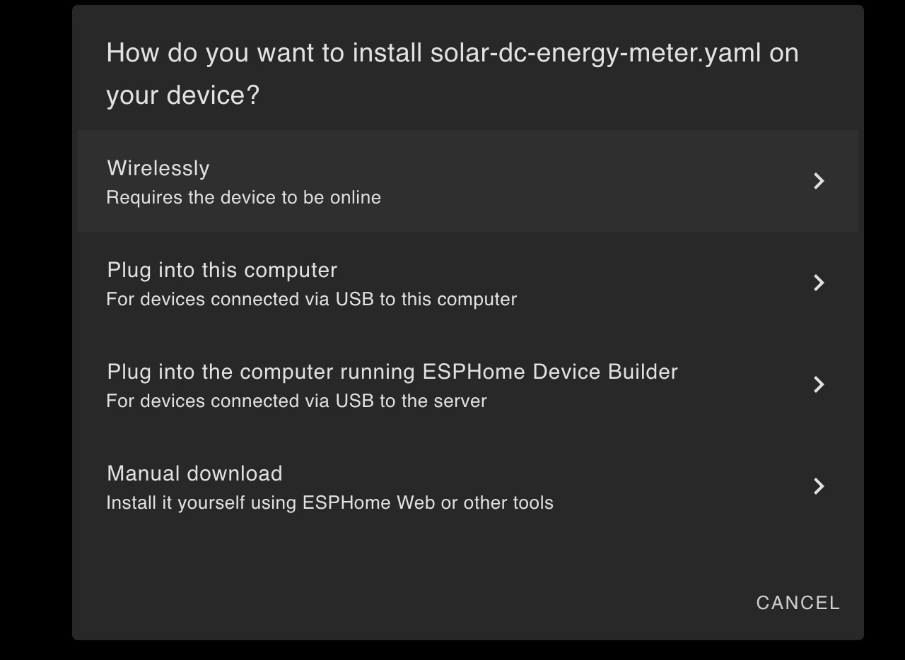
- Install the updated config wirelessly. If you're unable to install it wirelessly, then select last option manual download and try installing it manually using web.esphome.io.
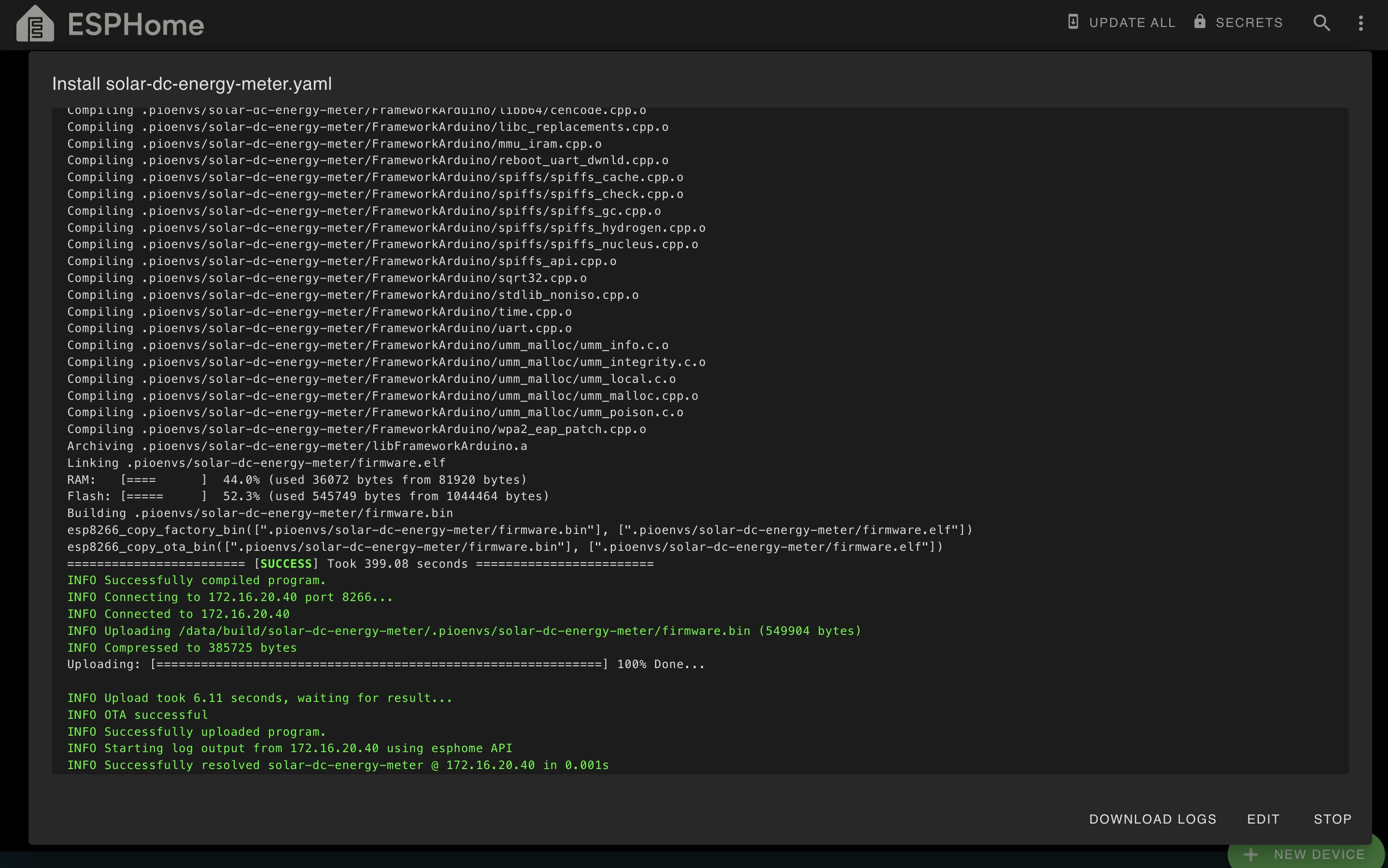
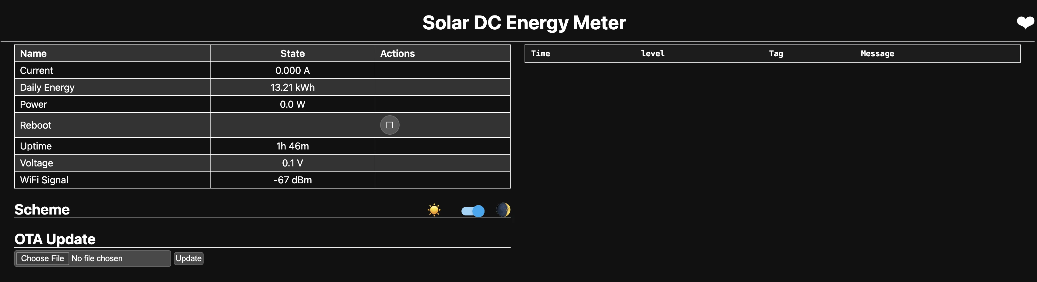
- Visit the ESP8266 IP assigned by your router (you can find this in your router's DHCP client list or in the ESPHome logs). You should be able to see something like this:
4. Add Device to Home Assistant
After successfully flashing your ESP8266 and confirming it's working through the web interface, you need to add it to Home Assistant to see all your solar/battery monitoring sensors.
4.1. Add Device
- Go to Settings
- Select "Devices & Services"
- Click the "+ ADD INTEGRATION" button
- Search for and select "ESPHome"
- Enter device details:
- Host: Enter the IP address of your ESP8266
- Port: Leave as 6053 (default)
- Click "Submit"
4.2. Verify Integration
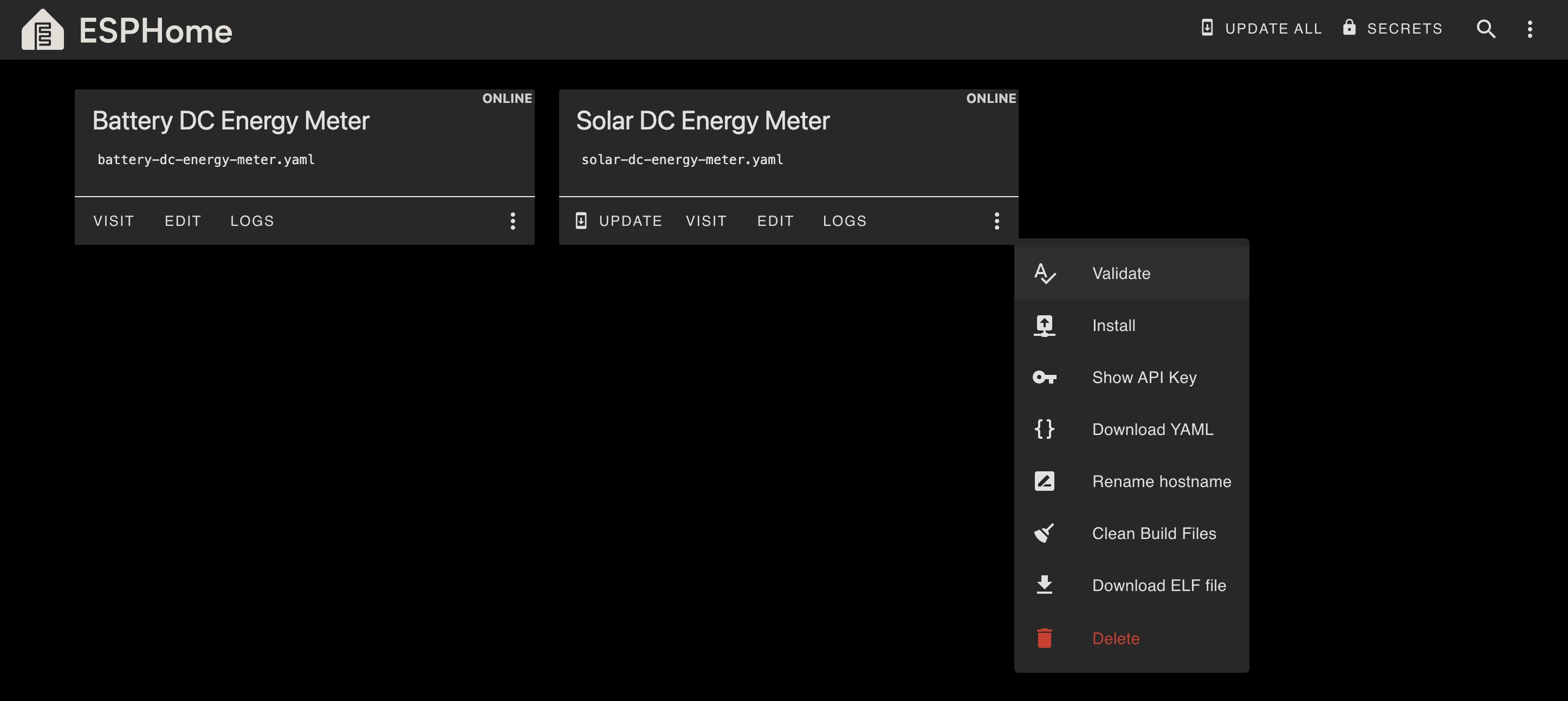
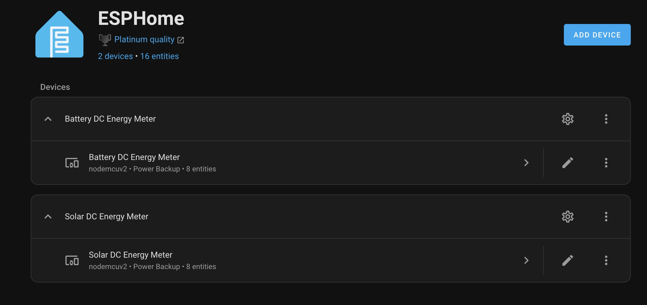
After successful integration, you should see the device listed like this.
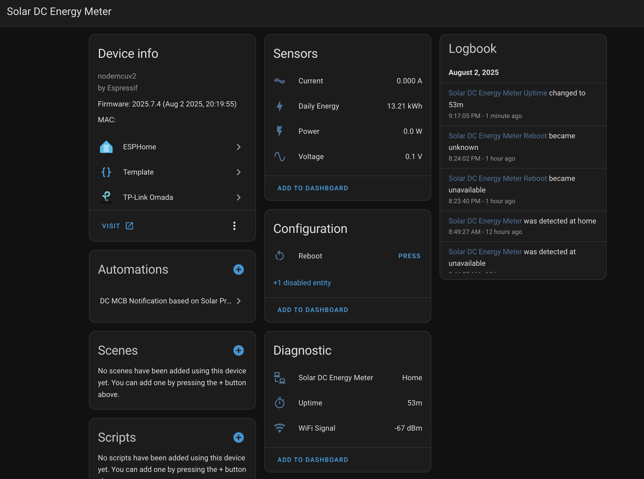
You can open the device details to view its entities and their values.
This setup gives you a professional grade solar monitoring system for under ₹2000 (~$20-$25) in components. Once working, you can create beautiful dashboards in Home Assistant to track your solar production or battery status, set up automations based on energy levels, and keep historical data for analysis.
The system is very reliable once properly configured and can run for months without issues. The key is getting the initial setup right, especially ensuring a stable power supply to the PZEM-017 and proper RS485 communication.
5. Common Issues and Solutions
5.1 No response from PZEM-017
- Check power: PZEM-017 needs 5-300V DC on its voltage terminals to operate. If you need to measure less than 7 volts, you must provide a 5V DC supply to the PZEM-017 through the micro USB port.
- Swap A/B wires: Try swapping the RS485 A and B connections
- Verify common ground: Ensure ESP8266, RS485, and PZEM-017 share ground
- Test with RS485-to-USB converter: Test the PZEM-017 directly using an RS485-to-USB converter to ensure it's working properly, since it has no LED indicator to show its status. In comparison, the RS485 adapter and the ESP8266 both have indicators that show whether they are functioning.
- Enable debugging: You can monitor the communication being sent and received over the UART bus by enabling debug mode. To do this, add the debug option in the UART configuration like this:
uart:
  tx_pin: GPIO15
  rx_pin: GPIO13
  baud_rate: 9600
  stop_bits: 2
  debug:
5.2 Boot issues or persistent TX light on RS485
- Ensure GPIO 15 pulled low during boot using 1k-5kΩ resistor to ground.
- Use different GPIO pins (and don't forget to update the configuration accordingly).